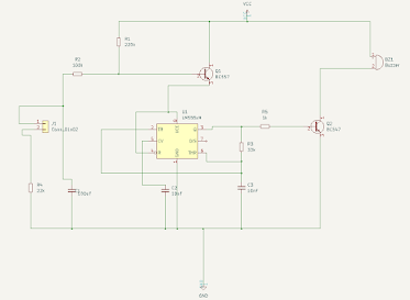
Working of the Project Connect the circuit as per the circuit diagram and apply the power supply. To turn “ON” the device, touch the “ON” plate with your finger and to turn OFF the device , touch the OFF plate. When power supply is applied to circuit, the device connected through the relay (we have connected a light bulb) remains OFF. Now, if we observe the circuit diagram, Pin 2 is pulled HIGH and Pin 6 is Pulled LOW. When we touch the ON plate, voltage at Pin 2 (Trigger Pin) of the 555 IC becomes LOW. As Pin 6 is already LOW, the output at Pin 3 becomes HIGH. Since this is connected to the Relay Module through the Transistor, the Transistor will be turned ON and it in turn activates the Relay. As a result, the device gets switched ON. At this point voltage at pin 6 is zero as it pulled LOW by default and voltage at Pin 2 is HIGH. Now, when you touch the OFF plate, the Pin 6 is supplied with +5V for a brief time and as a result, the output of the 555 Timer IC will become LOW. Th...