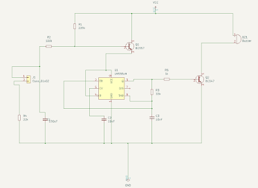
Overview: Mobile Phone Detector Circuit Mobile Phone Detector is a Circuit that detects the presence of Mobile Phone up to a certain range like 1.5 meter . It detects the phone when an incoming call or outgoing call is made or when an SMS is sent or received or any GPRS used . When the circuit detects an RF signal from an activated mobile phone, it gives an indication by switching ON an LED . The LED will start blinking and continues to blink until the incoming/outgoing signal stops. Mobile Phone detector can also be called as a Frequency Detector. Frequency Detector is simply a Current to Voltage Converter Circuit which detects the frequencies in between the range of about 800 MHz to 3GHz . Bill of Materials S.N. COMPONENTS DESCRIPTION QUANTITY 1 LM358 Dual Op-Amp IC 1 2 Resistor 1 KΩ 1 3 Resistor 100 K Ω 1 4 Resistor 220 K Ω...


Comments
Post a Comment