PCB Design - Mobile Phone Detector


Overview: Mobile Phone Detector Circuit
Mobile Phone Detector is a Circuit that detects the presence of Mobile Phone up to a certain range like 1.5 meter . It detects the phone when an incoming call or outgoing call is made or when an SMS is sent or received or any GPRS used.
When the circuit detects an RF signal from an activated mobile phone, it gives an indication by switching ON an LED. The LED will start blinking and continues to blink until the incoming/outgoing signal stops. Mobile Phone detector can also be called as a Frequency Detector. Frequency Detector is simply a Current to Voltage Converter Circuit which detects the frequencies in between the range of about 800 MHz to 3GHz.
Bill of Materials
| S.N. | COMPONENTS | DESCRIPTION | QUANTITY |
|---|---|---|---|
| 1 | LM358 | Dual Op-Amp IC | 1 |
| 2 | Resistor | 1 KΩ | 1 |
| 3 | Resistor | 100 K Ω | 1 |
| 4 | Resistor | 220 K Ω | 1 |
| 5 | Potentiometer/Trimmer | 2.2 M Ω | 1 |
| 6 | Capacitor | 1 µF, 16V (Electrolytic Capacitor) | 2 |
| 7 | Capacitor | 100 µF, 16V (Electrolytic Capacitor) | 1 |
| 8 | BC548 | NPN Transistor | 1 |
| 9 | LED | 5mm Any Color | 1 |
| 10 | Antenna | 15cm Single Strand Wire Antenna | 1 |
| 11 | Power Supply | 4.5V Battery/Adapter | 1 |
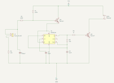
Mobile Phone Detector Circuit using Op-Amp
This circuit consists of an op-amp with some active-passive components. A LED is used for an indication of the presence of a cellphone. Op-amp is configured as Frequency Detector and its output is connected to a LED using NPN Transistor. The circuit diagram is given below. The circuit can be either assembled in a breadboard or in a Vero Board.

The circuit is built using LM358 Op-Amp IC and NPN Transistor BC548. You can check our previous project based on LM358 IC: Over Heat Detector
When a mobile phone is active, it radiates RF signal in the form of electromagnetic radiation. When the mobile phone radiates energy in the form of RF signal, Capacitor C2 absorbs it and used as an input to LM358 IC. The output of LM358 is connected to LED via Transistor which gets turned ON. Then the flashing of LED is observed. The potentiometer RV1 is used to adjust the sensitivity or range of the circuit. This is how you can make a Simple Phone Detector Circuit.

Comments
Post a Comment