Posts

PCB Design - Mobile Phone Detector

Image
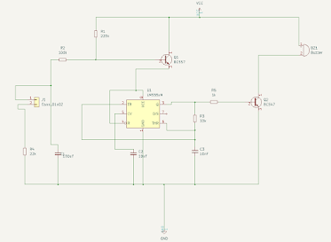
  Overview: Mobile Phone Detector Circuit Mobile Phone Detector  is a Circuit that detects the presence of  Mobile Phone  up to a certain range like 1.5 meter . It detects the phone when an  incoming call  or  outgoing call  is made or when an  SMS is sent  or  received  or any  GPRS used . When the circuit detects an  RF signal  from an activated mobile phone, it gives an indication by  switching ON  an  LED . The LED will start blinking and continues to blink until the  incoming/outgoing signal  stops.  Mobile Phone detector  can also be called as a Frequency Detector.  Frequency Detector  is simply a  Current to Voltage Converter Circuit  which detects the frequencies in between the range of about  800 MHz to 3GHz . Bill of Materials S.N. COMPONENTS DESCRIPTION QUANTITY 1 LM358 Dual Op-Amp IC 1 2 Resistor 1 KΩ 1 3 Resistor 100 K Ω 1 4 Resistor 220 K Ω...

PCB Design - Automatic plant irrigation system

Image
 

PCB Design - Darkness Detector using 555 timer

Image
 

PCB Design - Wailing seiren

Image
 

PCB Design - Bike Turning Signal Indicator

Image
 

PCB Design - Touch ON and OFF Circuit

Image
  Working of the Project Connect the circuit as per the circuit diagram and apply the power supply. To turn “ON” the device, touch the “ON” plate with your finger and to turn OFF the device , touch the OFF plate. When power supply is applied to circuit, the device connected through the relay (we have connected a light bulb) remains OFF. Now, if we observe the circuit diagram, Pin 2 is pulled HIGH and Pin 6 is Pulled LOW. When we touch the ON plate, voltage at Pin 2 (Trigger Pin) of the 555 IC becomes LOW. As Pin 6 is already LOW, the output at Pin 3 becomes HIGH. Since this is connected to the Relay Module through the Transistor, the Transistor will be turned ON and it in turn activates the Relay. As a result, the device gets switched ON. At this point voltage at pin 6 is zero as it pulled LOW by default and voltage at Pin 2 is HIGH. Now, when you touch the OFF plate, the Pin 6 is supplied with +5V for a brief time and as a result, the output of the 555 Timer IC will become LOW. Th...